d.
Set RANGE-FULL SCALE control to .001 and carefully
adjust BALANCE control for minimum meter deflection.
Normal meter deflection for zero input signal is
as follows:
RANGE
DEFLECTION
.001
less than 3/4 inch
.003, .01, .03, .1, .3,
less than 1/16 inch
1, 3
Suppressed
a. Set RANGE-FULL SCALE control to appropriate setting
(or higher) for voltage to be measured.
b. For "in-circuit" measurements, remove 500 Adapter and
attach Probe Tip to RF Probe. The Probe Tip is useful
for direct measurement to approximately 250 megacycles,
however, a short wire should be substituted for the
ground lead when using above 100 Mc to minimize the
effects of ground lead inductance. Above 250 mega-
cycles, the probe may be used directly without the
tip but the connecting leads must be extremely short
to avoid resonant effects, see Fig. 4.
c. Connect ground clip or wire to suitable ground and
connect tip to point where voltage is to be measured.
Alternatively measurement may be made using direct
connection (Fig. 4.).
d.
Read RF voltage on appropriate meter scale corresponding
to setting of RANGE-FULL SCALE control.
e.
To obtain readings in decibels, add the db (red scale)
meter reading to the db (red) setting of the RANGE-FULL
SCALE control. Although individual db readings have no
significance as absolute measurements, the difference
between two db readings is a useful way of expressing
voltage ratio.
f.
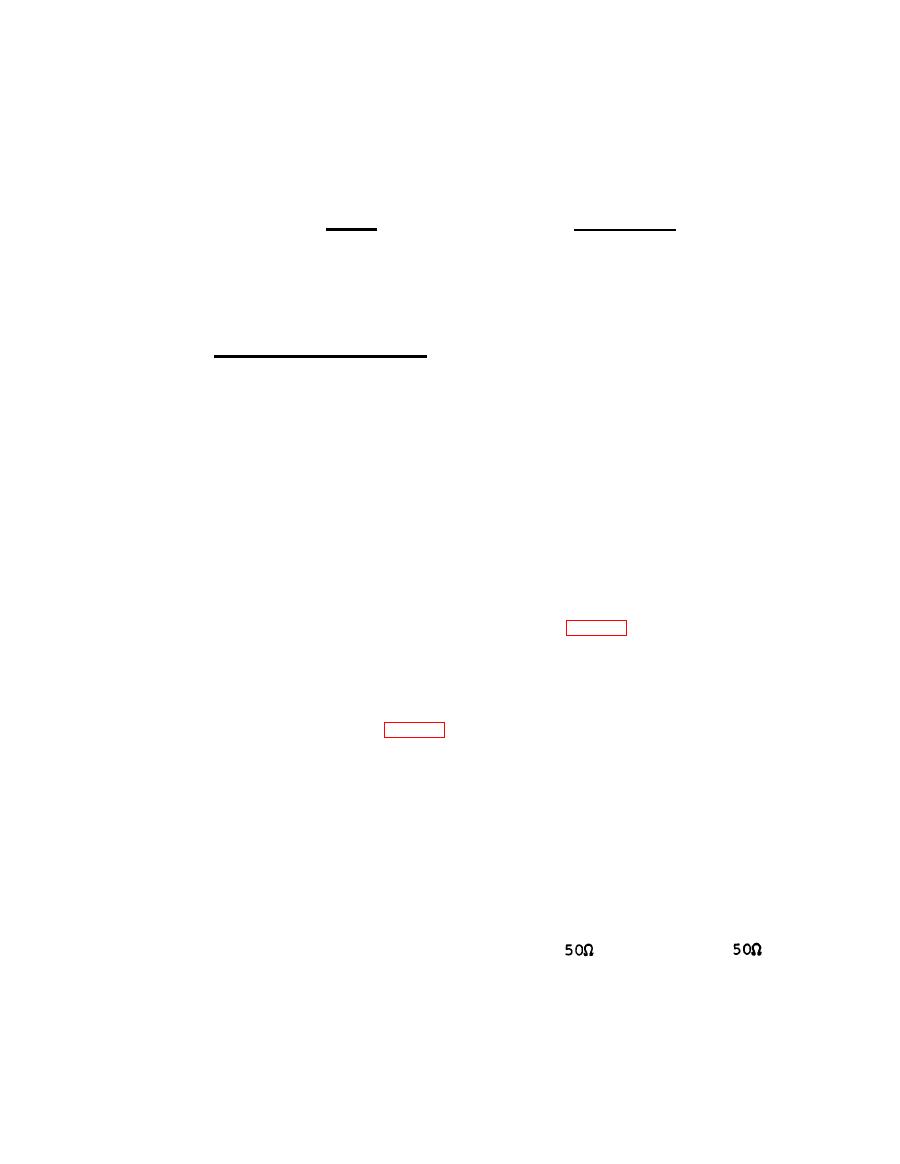
For terminated measurements in
systems, the
Adapter should be attached to the RF Probe. Always
AN/URM-145
a


