TM 11-6625-524-14-4
DETAILED DESCRIPTION, PROBE AND TERMINATIONS
a. Probe: The probe's spring-loaded construction guarantees positive contact
with the various threaded accessories. The built-in resistors are epoxy encapsu-
lated and the entire probe and cable assembly are sealed, with the exception of the
diode cartridge assembly. The probe should provide years of dependable service.The
d i o d e cartridge, being the only part subject to electrical damage, is easily re-
placed.
b. D i o d e cartridge: The diode cartridge employs two (2) special, low-capacity,
h i g h - s t a b i l i t y germanium diodes in a full-wave configuration for RF detection. The
measuring capability of the voltmeter covers RF voltages reaching from the square-
law region (100V to 30mV) to the region of linear rectification (1V to 3V). In the
square-law region, the voltmeter is true RMS responding, while in the linear region
i t is peak-responding. I n the 30mV to 1V "transition" r e g i o n , the diode character-
i s t i c s gradually change from RMS to peak. This non-linear characteristic is true
o f all diode rectifiers, regardless of design and manufacture. The voltmeter is
calibrated in terms of RMS on all 8 ranges.
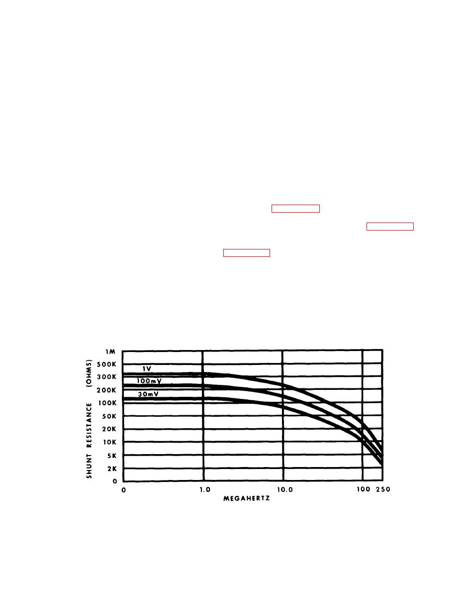
The diodes have characteristics the user of the voltmeter should be aware of:
1. The shunt resistance of the diodes (probe input impedance) varies in-
v e r s e l y with both signal level and frequency. (see figure 4-3)
2. T h e capacity of the diodes varies inversely with signal level. Probe in-
put capacity varies from approximately 1pf at 3V to 2.2pf at 10mV. (see figure 4-4)
c . Type BNC 50-ohm termination adapter: This is the most widely used termination
with a VSWR of less than 1.2:1 to 600MHz. It is not recommended for accurate
measurements above this frequency. (see figure 4-5) The termination has a 5 watt
power rating.
d. High impedance probe tip: This tip allows high impedance direct measure-
ments up to 250MHz.
Probe input impedance vs. level and frequency.


