TM 11-6625-524-14-4
The meter's input terminal will be shorted to ground when the voltmeter is switched
O F F . This helps to prevent electro-static build-up from damaging the meter move-
ment coil while in transit. It also facilitates in mechanically zeroing the meter
by removing all potentials from the meter movement coil.
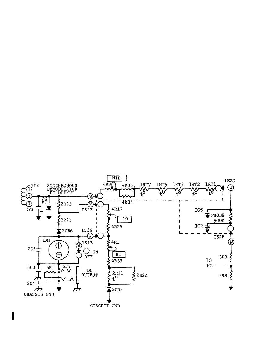
1. DC output: For external monitoring purposes, a 1.0V (1mA m a x . ) linear output
voltage is provided at output connector, 5J2. When the external D C output 3 circuit
p h o n e plug (furnished as a standard accessory) is inserted, the i n t e r n a l 2K load
(5R1) at 5J2 is disconnected. The external monitor must provide the 2K impedance
load-and should be within 1% accuracy to maintain rated' voltmeter specifications.
m. Power supply: The power transformer (2T1) has a
AC dual pri-
115V/230V
mary input. The full wave rectifier, 2CR1 and 2CR2, is connected to the center-
t a p p e d secondary. The rectifier's output is applied to the series regulator tran-
s i s t o r (2Q1). Reference voltage for both the series regulator transistor (2Q1) and
o u t p u t amplifier (2Q5) is provided by the reference amplifier (2Q3). A constant
c u r r e n t source, 2CR3 and 2CR4, maintains a constant bias at the reference ampli-
f i e r ' s base. The inverting amplifier (2Q2) will bias the series regulator tran-
s i t o r ' s base with an inverted reference voltage. A n adjustable voltage divider
a c r o s s the output amplifier's base permits adjustment of the series regulator's
o u t p u t . This electronically regulated power supply delivers a stable and virtually
r i p p l e free voltage source regardless of variations in power line voltage (103.5V
to 126.5V).
T o eliminate inter-action and possible oscillations between the various ampli-
f i e r boards circuits, local filtering is provided at the AC amplfying stages and
DC modulator driver.
L i n e a r i z i n g correction network.
4-4 Change 1


