TM
11-6625-524-14-4
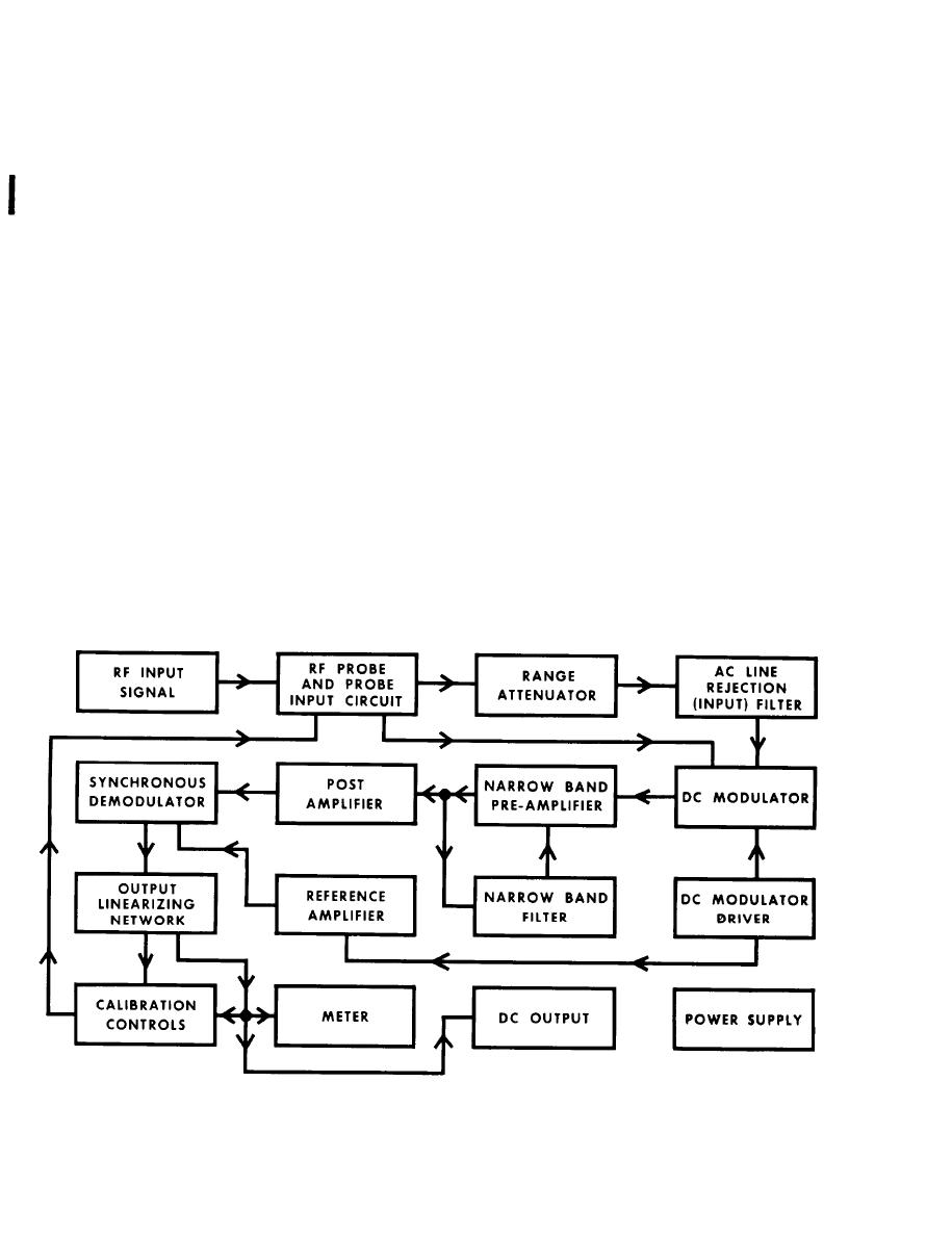
d. DC modulator: The DC modulator (3G1) is a plug-in solid state photo chopper.
It converts the incoming DC signal into a nearly symmetrical square wave with a
c a r r i e r frequency of 94Hz. T h e r m i s t o r s , located in the DC modulators LED driver
c i r c u i t s , optimize the modulator's performance at ambient temperature extremes.
e. D C modulator driver: The driver is a 2 transistor (3Q1 and 3Q2)oscillator
and is adjusted to 94Hz by means of FREQ. ADJ. control (3R11). The oscillator's
square wave output powers both the DC modulator and synchronous demodulator via
t h e reference amplifier.
f . N a r r o w band pre-amplifier and filter: The pre-amp utilizes a high-impedance
FET (309) input. Clamping diodes 3CR3 and 3CR4, at the FET's gate, minimizes over-
load damage. The three-stage conventional R/C coupled, common emitter amplifier con-
sists of transistors 3Q10, 3Q11 and 3Q12 and their associated circuitry. A tuned
p a r a l l e l "T" narrow band filter network, from the collector of 3Q12 to the base of
3 Q 1 0 , narrows the amplifier's bandwidth to further improve the signal-to-noise
ratio.
9. P o s t amplifier: T h i s amplifier provides further amplification of the pre-
a m p l i f i e r ' s o u t p u t . The two-stage conventional R/C coupled, common emitter ampli-
f i e r consists of transistors 3Q13 and 3Q14 and their associated circuitry. A GAIN
A D J U S T control (3R53)at 3Q13's input will adjust the post amplifier's output to
optimum. Maximum post amplifier gain is used for 0.001V full scale and 0.003V full
scale ranges while a reduced gain is used for the other ranges. Gain reduction is
o b t a i n e d by paralleling resistor 3R54 with resistor 3R55.
Change 1


