TM 11-6625-444-14-2
Section II. TOOLS AND TEST EQUIPMENT
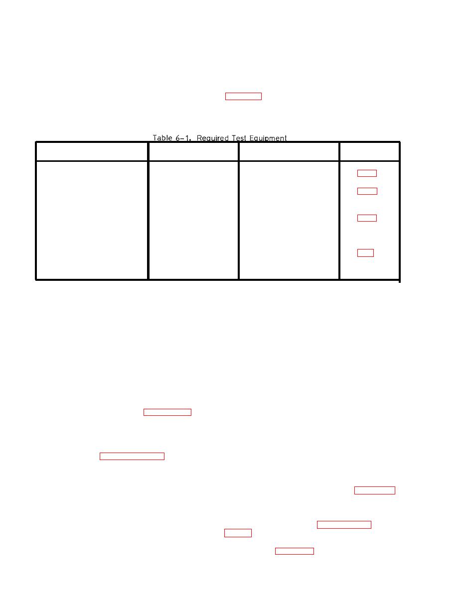
required for maintenance of the voltmeter (see
This section contains a listing of test equipment
Reference
Nomenclature
Common Name
NSN
Paragraph
Dc voltage calibrator
John Fluke Model 332B
6625-00-150-6994
Ac voltage calibrator
John Fluke Model
5200A/5215A
H.P. Model 180D
Gen. Rad. W10MT3AS3
Variable transformer
6120-00-168-3705
AN/USM-451
CP-772 A/U
Frequency counter
Section III. TROUBLESHOOTING
(b) Dc Volts Attenuator/Buffer (A1)
6-5. General
(c) A/D Converter (A1)
Troubleshooting information supplied in this
(d) Up/Down Detector (A1)
section is in the form of flow charts that will fa-
cilitate locating a defective assembly or com-
(e) Function Select Logic (A2)
ponent rapidly.
(f) Range Select Logic (A2)
(g) Digital Counter/Display Drivers (A2)
First check for loose plug-in assemblies, im-
p r o p e r l y mated connectors, (figures 6-2 and
(h) Autorange Circuits (A2)
6-3) broken wires, physically damaged (burned
(i) Clock Circuits (A2)
or broken) components and other obvious prob-
lems. Next, the characteristics detailed in the
( j ) Display (A3)
Performance Assurance Checks of Section V
(k) True Rms Converter (A7)
( b e g i n n i n g with paragraph 6-13) should be
checked and any discrepancies noted. This will
(l) D C Ratio Amplifier (A9)
serve as an aid to pin-pointing the source of
trouble.
With the aid of the flow charts, figure 6-4 to
6-7, it should be possible to isolate the fault to
one of these sections. Once the problem has
been reduced to a major section, refer to the
applicable schematic(s), figures FO-2 through
The voltmeter consists of the following major
sections (also see Maintenance Allocation Chart:
isolate to the component level. Also refer to the
logic tables in Chapter 5, Section II.
(a) Power Supply (A1, A2)


