TM
11-6625-2981-14
OPERATION
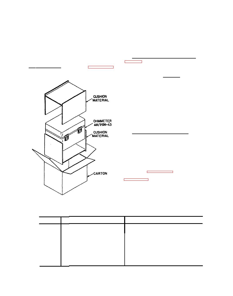
flaps.
Remove
the
cushion
material
INTRODUCTION.
from
the
top
and
sides.
The
ohmmeter
will
operate
in
the
Remove
the
range
of
0
to
1000
Megohms,
primarily
for
use
with
electric
equipment
and
machines.
b.
Inventory
of
Equipment.
Refer
to
v e r i f y that
you
have
1-2 and
SERVICE UPON RECEIPT.
received
all
items
shown
in
that
table.
a . Unpacking.
Refer
to
Cut
the
tape
holding
the
flaps
on
the
top
of
the
carton.
Open
the
four
WARNING
DANGEROUS
VOLTAGES
EXIST
IN
THIS
EQUIPMENT
not
come
in
contact
with
DO
test
leads
or
terminals
during
operation.
Potentials
as
high
as
550
Volts
exist
during
operation.
DON'T
TAKE
CHANCES!
c.
Operational
Checkout.
Pointer
s h o u l d be
u n br o k e n .
Glass
over
indi-
cator
panel
should
not
be
cracked.
Check
terminal
posts
for
cracks.
Place
a
short
across
terminals,
crank
handle,
meter
should
read
zero
with
crank
turning
at
approximately
150
rpm.
CONTROLS
AND
INDICATORS.
Controls
and
indicators
are
illus-
trated
in
Control
and
indicator
functions
are
listed
in
EL6TW003
Packaging
Diagram
Controls
and
Indicators
Function
Name
Item
Powers
Crank
handle
1
Indicates
Pointer
2
External
ground
connection
Binding
post
(Black)
3
External
line
connection
Binding
post
(Red)
4
External
guard
connection
5
Binding
post
(Green)


