e. Insert the tube in its proper test socket
and perform the procedures in paragraph 17b
through d .
f. O b s e r v e t h e f i l a m e n t o f t h e t u b e ; b o t h
sides should be lighted.
g. S e t t h e P O W E R s w i t c h t o t h e O F F p o s i -
tion,
and
set
the
FILAMENT
VOLTAGE
switch to 6.3.
h. S e t t h e l e f t a n d r i g h t F I L A M E N T s e l e c -
tor
switches
to
K
and
V,
respectively.
i. P e r f o r m
the
procedures
in
17b through d .
j. O b s e r v e
the
filament
of
the
tube;
only
one-half the filament should be lighted.
k. S e t t h e P O W E R s w i t c h t o t h e O F F p o s i -
Gas
Test
tion,
and
set
the
left
and
right
FILAMENT
Pushbuttons 4 - GAS 1 and 5 - GAS 2 are
selector switches to E and Z, respectively.
used when testing amplifier tubes for gas con-
l. P e r f o r m t h e p r o c e d u r e s i n p a r a g r a p h
17b
tent.
Multipurpose
tubes
are
tested
for
gas
through d .
only on the amplifier sections; the gas test does
m . Observe
the
filament
of
the
tube;
the
other half of the filament should be lighted.
Allow tubes of the filament type to warm up be-
n. If
the
tube
shows
filament
fore testing the tube for gas content.
proceed to test the tube in accordance with the
a. P e r f o r m
the
procedures
in
paragraph
instructions
in
through
22.
17a through d and f .
b. Set the controls as indicated in the test
Reading Meter
data book.
The meter scale is calibrated in divisions
c. Insert the tube in the proper test socket
from 0 to 120. When the proper pushbutton is
and set the POWER switch to ON.
depressed, the meter pointer will indicate the
d. H o l d
down
pushbutton
4 - GAS
1
and
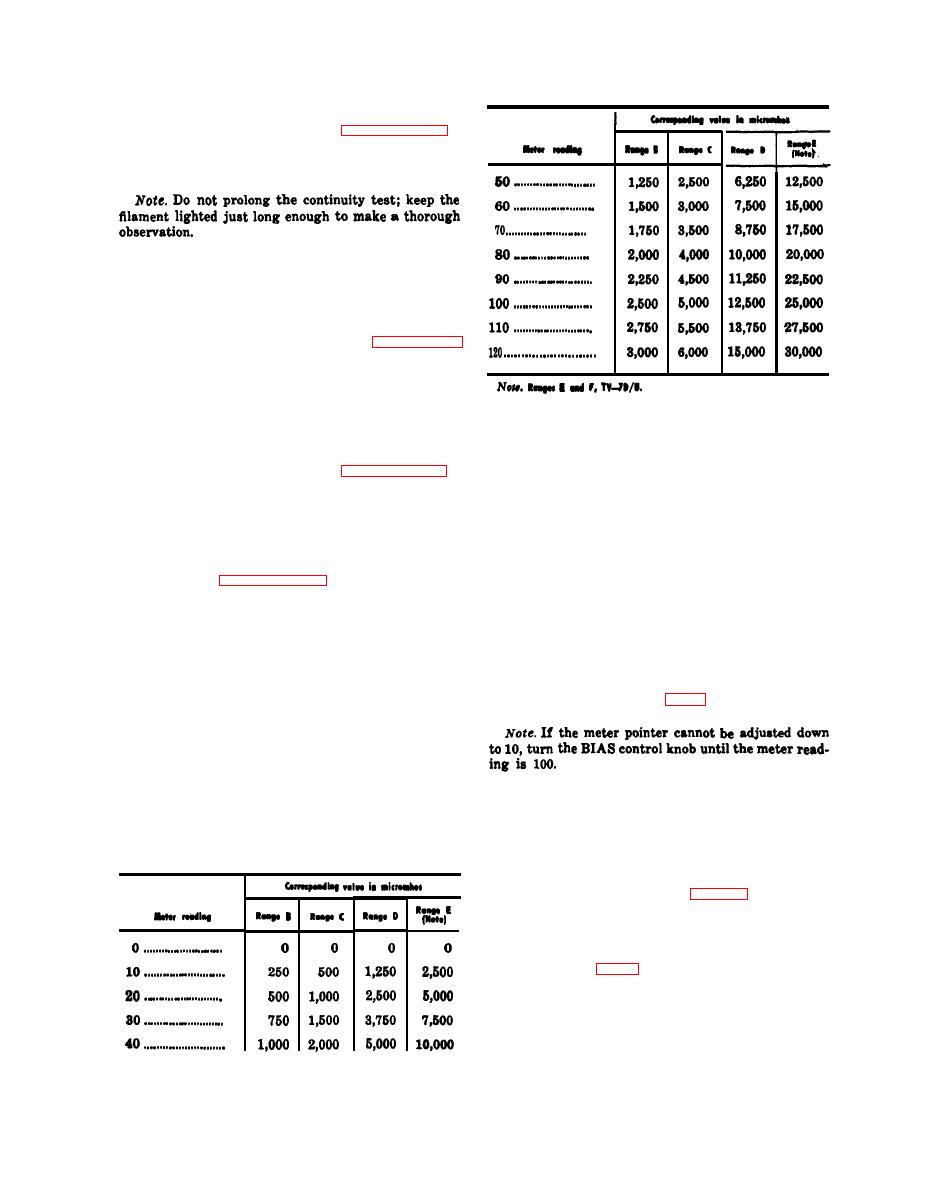
condition of the tube under test as a numerical
adjust the BIAS control (fig. 6) until the meter
value. The numerical value of the meter read-
pointer indicates 10 on the scale.
ing is then compared to the minimum accepta-
ble value in the M i n v a l u e column
in
the
test
data
book.
If
the
number
indicated
on
the
meter
is
less
than
the
listed
minimum
value,
e. H o l d d o w n p u s h b u t t o n 4 - G A S 1 a n d
the
tube
should
be
replaced.
The
following
press pushbutton 5 - GAS 2.
chart may be used to convert the numerical
f. I f
the
tube
contains
gas,
the
meter
value of the meter reading to mutual conduct-
pointer will move up the scale. A movement of
ance in micromhos.
more than 1 division on the scale indicates a
gassy tube.
g. Turn
off
the
test
set
26).
Noise
Test
The NOISE test jacks on either side of the
SHORTS lamp (fig. 6) are used when testing
electron
tubes
for
noise.
A
radio
receiver
or
an audio amplifier with a loudspeaker, and a
set of test leads, are required to perform the
test.


