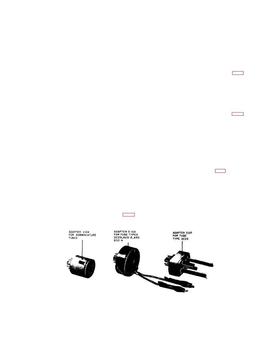
be tested in the OCTAL socket of the test set.
SCREEN,
CATHODE,
and
SUPPRESSOR
A spring locking action grips the leads of the
selectors are listed in this column. The settings
tube
after
they
are
inserted
in
the
adapter.
are
shown
in
the
same
order
in
which
the
Pull the two tabs upward to open the lock be-
switches appear on the panel, listing first the
fore
inserting
the
leads.
The
lock
is
secured
two
FILAMENT
selectors
and
then
continuing,
by pressing down on the two tabs until a click
from left to right, with the remaining selectors.
is heard.
d. Bias. This
column
lists
the
setting
for
the
BIAS
control.
b.
Adapter
E105. Adapter
E105
(fig.
e. Shunt. This column lists the setting for
enables tube type 3E29, 829-B, or 832-A to be
the
SHUNT
control.
Setting
of
this
control
is
t e s t e d in the OCTAL socket of the test set. The
required
only
when
the
FUNCTION
SWITCH
adapter consists of a special socket for these
is in the RANGES A SHUNT position.
tubes mounted on an octal base. The two leads
on the adapter connect to the two plate caps
f. Range. The
settings
for
the
FUNCTION
of the tube under test.
SWITCH are listed in this column. The letters
A through E (A through F, TV-7D/U) corres-
c.
Adapter
E107. Adapter
E107
(fig.
pond to the RANGES markings for the FUNC-
enables tube type 2C39 (a lighthouse tube) to
TION
SWITCH.
be tested in the OCTAL socket of the test set.
g. Press. Under this heading are listed the
The three pairs of spring contacts, from the
test pushbuttons that are used for the various
center outward, connect to the cathode and one
tube types and their individual sections in the
side of the filament, to the grid, and to the
case of multipurpose tubes.
plate, respectively, of the tube under test. The
center contact connects to the other side of
h.
Min
Value. The
minimum,
numerical
the filament of the tube under test.
values of meter indication for the various tubes
and
individual
sections
of
multipurpose
tubes
Adapters
(TV-7D/U).
d. Socket-Saver
are shown in this column. Any tube showing
Three socket-saver adapters (fig. 7) are in-
a meter reading less than the value indicated
cluded
with
each
TV-7D/U:
one
7-pin
minia-
in this column should be replaced.
ture, one 9-pin miniature, and one octal. The
i. Notations. Special information pertain-
adapters are installed in their corresponding
ing to particular tube types is listed under this
sockets and receive the wear rather than the
heading.
permanent socket. When worn so that satisfac-
tory contact can no longer be made, the socket-
Adapters
can be replaced without
saver adapters
disconnecting
the
leads
from
their
respective
a.
Adapter
E104. Adapter
E104
(fig.
test socket.
enables subminiature tubes with long leads to
TM6625-274-12-7


