TM 9-4935-282-34
803D
SECTION III
THEORY OF OPERATIONS
dials until it matches the unknown voltage as indicated by the
3-1. GENERAL
vtvm. All AC measurements are made by first converting the
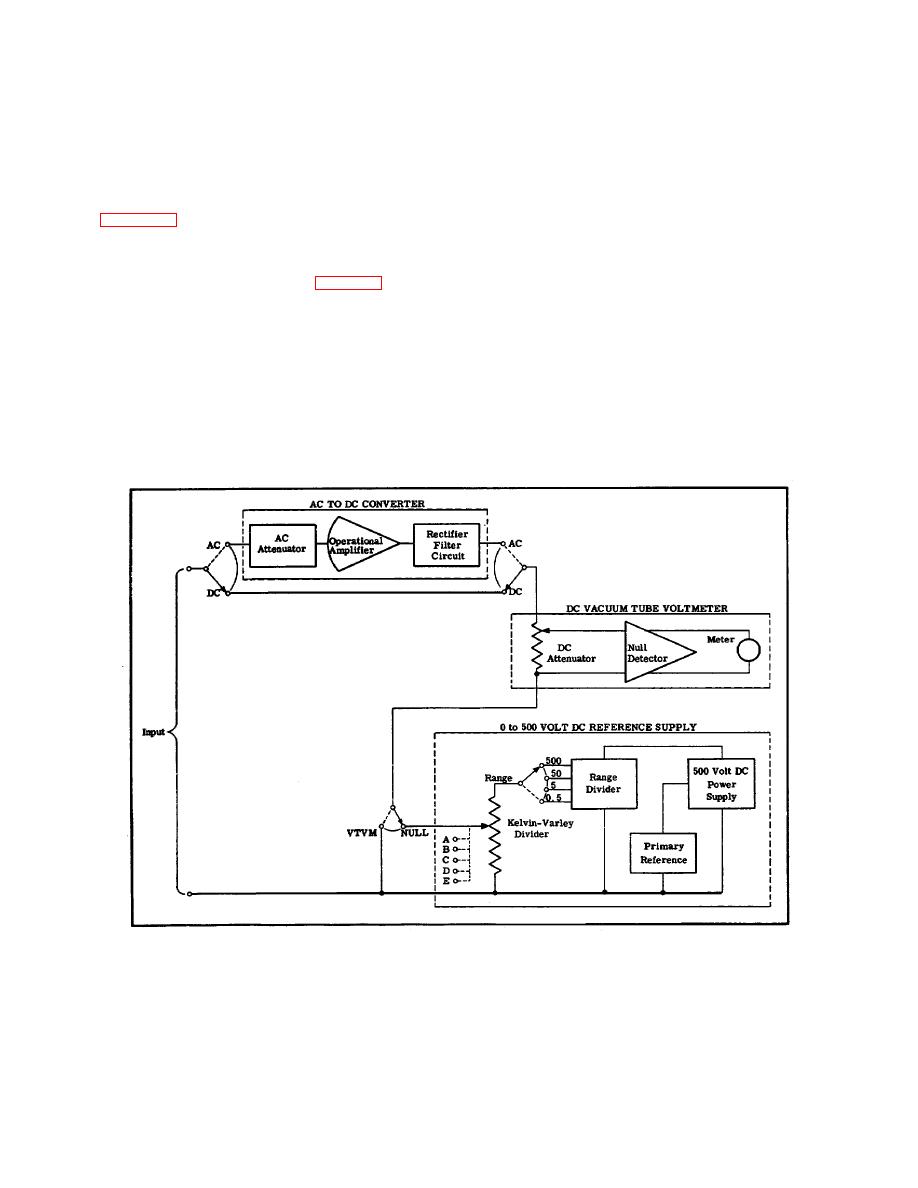
a. Figure 3-1 shows the block diagram for the 803D
AC input voltage to a DC voltage by means of the AC to DC
AC/DC Differential Voltmeter. As seen in this figure, the circuit
converter. The 803D then operates essentially the same as for
consists basically of an AC to DC converter, a DC vacuum
approximate and accurate DC measurements.
tube voltmeter (vtvm), and a 0 to 500 volt DC reference supply.
c. In order to provide for a more complete understanding
Refer to the functional schematic following section VI for more
of the 803D voltmeter, the following paragraphs describe each
detail. This schematic is designed to aid in the understanding
section of the circuit in detail.
of circuit theory and troubleshooting. The signal flow is from
left to right and the components are laid out in a functionally
3-2. DC VACUUM TUBE VOLTMETER
logical manner.
b. The overall operation of the 803D may be
a. GENERAL.
The DC vtvm is composed of an
summarized as follows. To measure the approximate value of
attenuator, a null detector, and a meter. The heart of the DC
a DC voltage, the unknown voltage is connected directly to the
vtvm is the null detector in which the DC signal input is
DC vtvm. To accurately measure a DC voltage, the unknown
modulated by an electromechanical chopper, amplified by a
voltage is connected across the series combination of the DC
convention
four
stage
resistance-capacitance
vtvm and the 0 to 500 volt DC reference supply. The reference
coupled amplifier, rectified by the chopper, and
supply voltage is then adjusted with the five voltage readout
Figure 3-1. 803D AC/DC DIFFERENTIAL VOLTMETER BLOCK DIAGRAM
3-1


