TM 55-492-231-14
SUPPRESSION.
a. Place a radio receiver that is in good oper-
ating condition in a position not more than 5
feet from the tester. A wide band receiver with
a frequency range of 0.15 in 1000.0 megacycles
is preferred.
b. Start the tester and tune the receiver in to
three widely separated frequencies at maximum
volume. Use frequencies that are free of signals
with strong carriers so that the receiver will be
in its most sensitive operating condition.
c. When the tester is operating, listen to the
receiver for interference which ceases when the
tester is stopped and which indicates that the
suppression is defective.
60. REPLACEMENT OF SUPPRESSION
COMPONENT.
a. Removal.
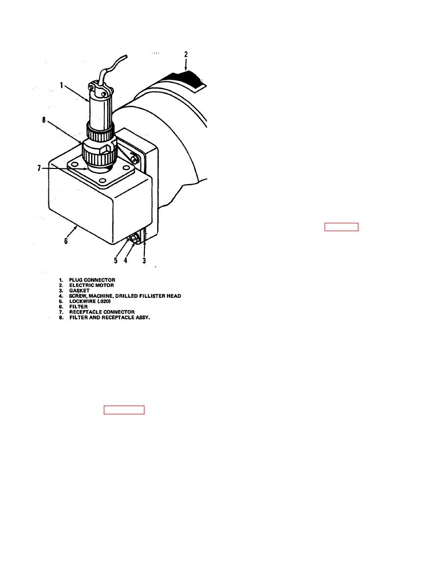
(1) Disconnect plug (1, figure 19) from re-
ceptacle (7).
(2) Cut lockwire (5) and remove from
Screws (4).
(3) Remove screws (4) securing filter (6)
to electric motor (2) and remove filter and gas-
ket (3) from motor.
b. Installation.
(1) Place gasket (3) and filter (6) in posi-
tion on motor (2) and secure with screws (4).
(2) Secure the top two screws (4) together
and the bottom two screws (4) together with
AV 001480
the lockwire (5).
(3) Install the plug (1) on the receptacle
(7).
Section VI. PNEUMATIC SYSTEM
from the sump flows through two pressure con-
61. GENERAL.
trol valves (16 and 17). The pressure IN-
The pump (19, figure 11) serves the dual
CREASE valve (17) controls the amount of air
function of developing pressure as well as vac-
permitted in the system and the pressure DE-
uum for operation of the tester. In the pressure
CREASE valve (16) opens the line to the ambi-
section a mixer of air and oil is pumped into
ent air, allowing system pressure to bleed off.
the reservoir (33) where the oil and air are
The available pressure level, as fixed by the con-
separated. The separated oil drops to the bottom
trol valves is sent to the pressure relief valve
of the reservoir where it is fed to the pump for
(14) and PRESSURE selector valve (31). Setting
lubrication purposes, the air being forced out at
the PRESSURE selector valve at the desired test
the top of the reservoir under pressure, The
position completes the circuit to the instrument
pressurized air, after going through the check
under test and simultaneously connects the in-
valve (32) whose function it is to prevent oil
strument under test and the master instrument
from entering instrument lines during operation,
to one of the pressure relief valves (12 or 13).
enters an oil sump (15) and passes through a
filter which is an integral part of tire sump. Air
The pressure relief valve (14) is in the line at


