THEORY OF OPERATION
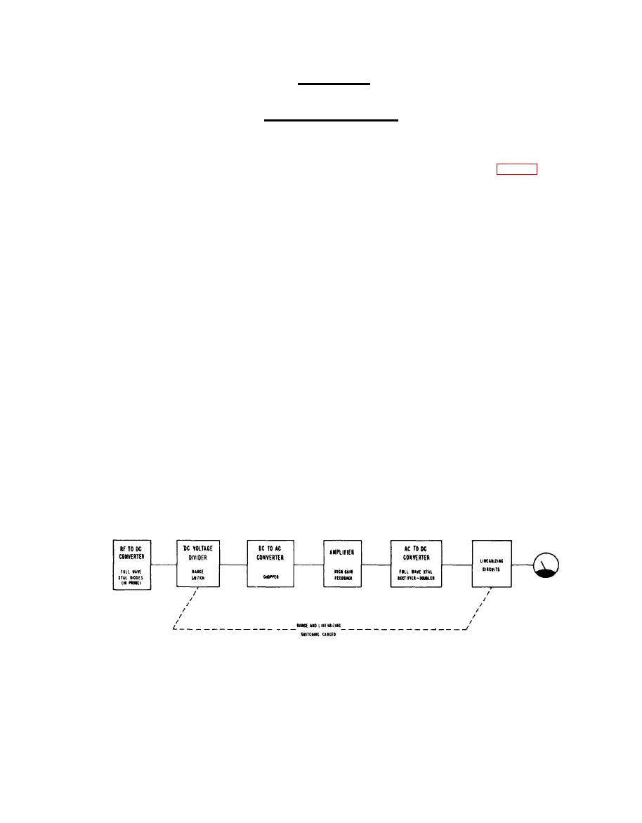
4.1 An understanding of the operating features of the RF Volt-
meter may be obtained by a study of the block diagram (Fig. 5)
in conjunction with the following description.
The radio frequency voltage to be measured is recti-
fied in the RF Probe by means of a full wave germanium diode
rectifier circuit. The resulting DC potential is then attenu-
ated as required before conversion to 60 cycle AC by the chopper.
This AC signal is then amplified in a narrow band feed-back
stabilized amplifier prior to its re-conversion to DC for use in
actuating the meter.
The germanium diodes used in the RF Probe have been
carefully selected for several characteristics. As the selected
diodes do not all exhibit the same rectification efficiency
characteristics, it becomes necessary to adjust each meter range
to match individual probe diodes. The range adjustments consist
of individual non-linear circuits shunting the output meter
circuitry. As the RANGE switch is set to the required test volt-
age position the appropriate non-linear adjusting circuit is
automatically shunted across the output. It is also important to
understand that the non-linear output circuitry is designed to
compensate for the non-linear characteristics of the probe diodes
when operating at levels below 0.3 Volt.
BLOCK DIAGRAM OF RF VOLTMETER
AN/URW-145
a


