TM 11-6625-524-14-4
(9) Measure +7.7V to +9.3V.
(10) Disconnect the DC multimeter. Connect the oscilloscope, set to 1
millivolt/centimeter, between 2TP1 and 2TP2.
(11) Measure 0.5mV to 0.0mV of ripple.
( 1 2 ) Readjust variable transformer's output for 103.5V. There should be
no noticeable change in the ripple amplitude.
( 1 3 ) Readjust variable transformer's output for 126.5V. There should be
no noticeable change in the ripple amplitude.
( 1 4 ) Readjust variable transformer's output for 115V.
PRE-AMPLIFIER AND POST AMPLIFIER TEST
Test equipment.
a.
(1) Oscillator
(2) AC voltmeter
(3) Oscilloscope
b.
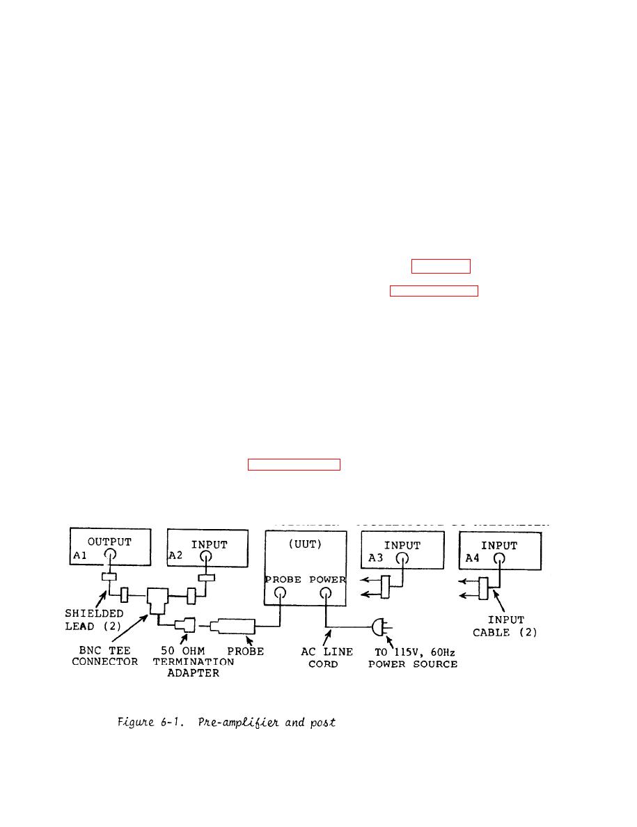
Test connections: Connect the equipment as shown in figure 6-1.
Procedure:
c.
P r o p e r l y shield the voltmeter (U.U.T.),(see paragraph 5-2).
(1)
s e t to 0.001 volt full scale range position, adjust the oscillator's output to
1mV.
the POWER switch is set to ON. Set the RANGE switch to the
(3) Verify
0 . 0 0 1 volt full scale range position.
( 4 ) Connect the oscilloscope, set to 5 volt/centimeter, from amp l i f i e r
board terminal (3TP7) to chassis.
( 5 ) Disconnect oscillator from probe. Adjust the SET REF control v o l t -
meter for minimum amplitude reading on the oscilloscope and should read 1.7 V to
2.3V P-P.
( 6 ) Reconnect the oscillator to the probe. With 1mV applied to the probe,
measure on the oscilloscope 13.5V to 16.5V P-P.
( 7 ) Disconnect oscilloscope. Leave other equipment connected in order to
p e r f o r m the voltage accuracy test, paragraph 6-5.
amplifier test setup.
.


