TM 11-6625-444-14-1
b. Power Supply Voltage Measurements. Each
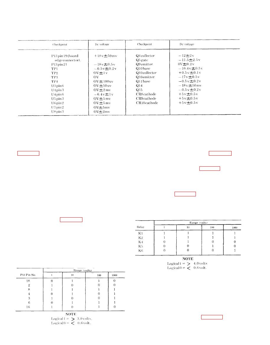
(3) Incorrect logic indications can be caused
of the supply voltages for the ac converter is
by misaligned connector pins; faulty FUNCTION
measured at the pin connectors of board edge
switch; defective range counter on the display pcb;
connector P13. This check verifies only presence of
defective RANGE switch; defective ac converter
relay gates; or a short circuit between ac converter
operating voltages. A detailed check of the
control lines.
voltmeter power supply voltages will be found in
help in locating defective relays or associated relay
(1) Connect the differential voltmeter between
driver circuits. If the voltage across the relay coils
P13 pin 19 and common (shield); the indication
does not appear as indicated in table 7-4, the relay
should be + 18 vdc.
drive circuit is at fault. Perform the command
(2) Connect differential voltmeter between P13
voltage measurements in c above before making
pin 21 and common; the indication should be - 18
this test. If the coil voltages are correct, but a
vdc.
relay fails to respond, the relay is defective. Logic
c. Command Voltage Measurements. Check for
1 and 0 is used in table 7-4. A logic 1 indicates a
proper command voltages for ranging in the ac
measured voltage of more than 4.0 volts and a
converter as follows:
logic 0 indicates a measured voltage less than 0.6
(1) Be sure that VAC pushbutton is
volt .
depressed.
(2) Connect the differential voltmeter between
P13 pins listed in table 7-3 and common. The
measured voltages should agree with the logic
symbols opposite the pin number and under the
voltage range heading. A logical 1 (one) equals a
measured voltage more than 3.0 volts and a logical
0 (zero) indicates a measured voltage less than 0.6
volt. Refer to (3) below for possible sources of
trouble if a logic indication is wrong.
7-16. Circuit Isolation
Turn the voltmeter on and allow it to operate for
at least 10 minutes. Erroneous indications can
occur if sufficient warmup is not allowed.
a. Disconnect the voltmeter from the power
source. Remove the top and guard covers. Extend
the ac converter from the voltmeter inner chassis
with the extender card provided (para 7-13).
b. Connect the voltmeter to the power source
Change 1


