TM 11-6625-444-14-1
I
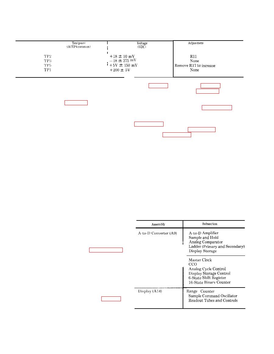
logic (fig. 6-6), and display (fig. 6-7). The test
point locations are shown in figure 6-1. Since each
this section is contained in both the buffer (All)
assembly performs a number of separate func-
and active filter (A10) assemblies. Test point
tions, they are divided into the independent
locations are shown in figure 6-1. To determine if
for
subsections
shown in
a trouble exists in the analog section, proceed as
troubleshooting. Troubleshooting of the digital
follows:
section is performed in the sequence shown in
(1) Connect a battery powered differential
voltmeter to A10TP4 () and TP3 (+).
and signals referenced in figures 6-14 and 6-15 are
(2) Select the 10 volt range and VDC function
contained in figures 6-16 through 6-22. Included
on the voltmeter.
with each waveform is the applicable test point
(3) Turn on the voltmeter and then apply a
and timing relation to other waveforms. All
+10V DC input to its INPUT terminals.
(4) Verify that the differential voltmeter
in the continuous measurement mode.
indicates -10V DC is present at A10TP4 and
NOTE
TP3.
The storage cycle can be by passed if there
( 5 ) Apply full-scale input voltages on
is a suspicion that it is faulty (usually
selected ranges of 1,100, and 1,000 volts. Each
indicated by flashing digits) by jump-
range shall produce the same voltage specified in
ering A1TP5 (+5V) to A14TP2. If the
step (4).
readout is then observed to be correct, the
NOTE
storage cycle circuitry is faulty. If not,
For inputs of less than full-scale on any
the trouble lies elsewhere.
range, the voltmeter will produce a
proportionally less voltage at A10TP4
and TP3. For example, a +10V DC input
in the 100-volt range will produce -1V
DC.
(6) If the voltage at A10TP4, and TP3 is not
correct, the trouble is in the analog section which
consists of the buffer and active filter assemblies.
Applicable troubleshooting procedures for each of
these assemblies are contained in paragraph 6-8.
If the voltage at A10TP4 and TP3 is correct, the
section.
digital
lies
in
the
problem
Troubleshooting procedures for the digital section
are contained in d below.
NOTE
Remove t h e ratio input (A3) when
troubleshooting the digital section.
is contained in the A-to-D converter (fig. 6-5)


