TM 11-6625-3059-10
AM MEASUREMENT
Step (1)
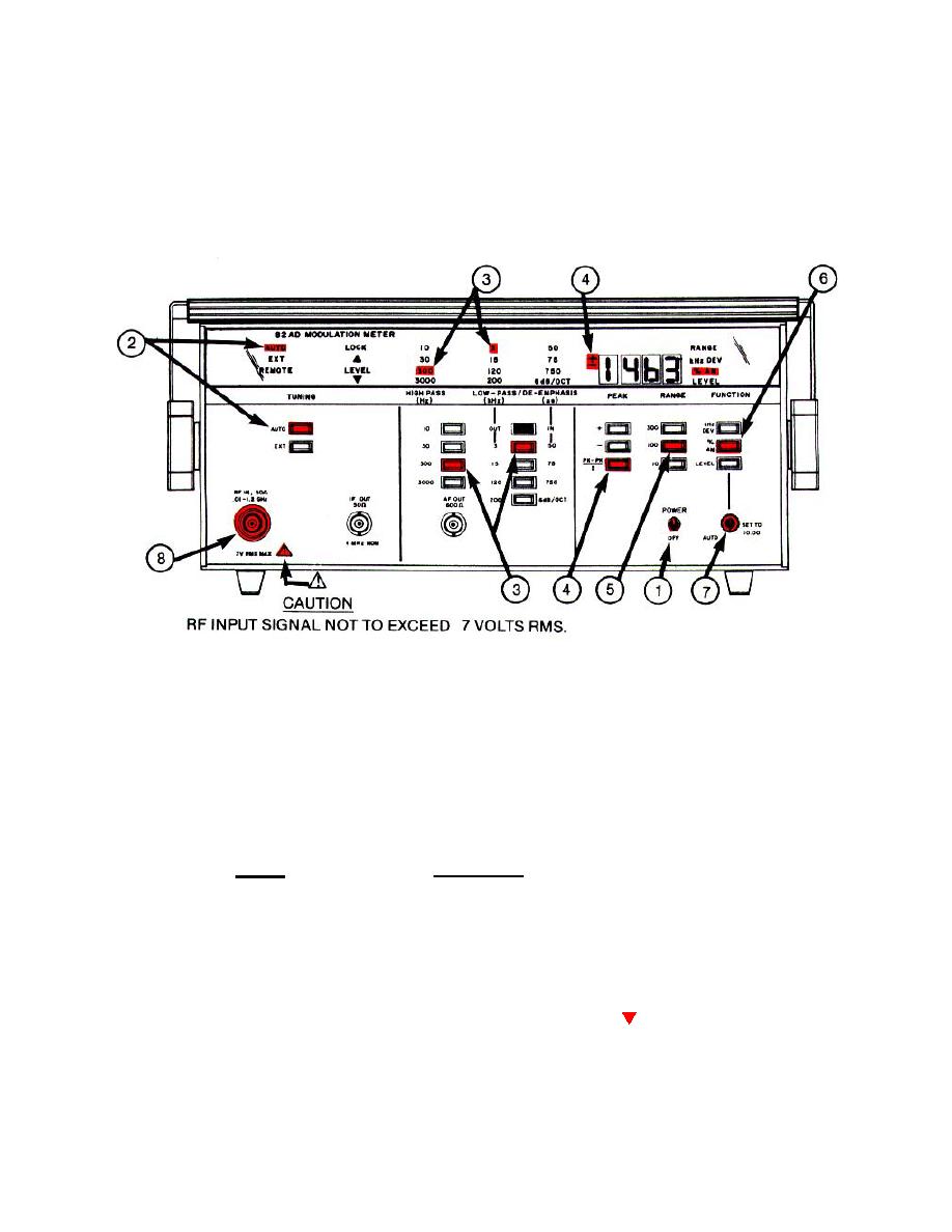
Place POWER-OFF switch in POWER position and allow 1 minute warmup
NOTE
In steps (2) through (4) and (6) below the annunciators will light as the switches are depressed.
Step (2)
Depress the TUNING AUTO switch.
Step (3)
Select the desired measurement bandwidth, using the minimum bandwidth consistent with the modulating
frequency. For example, for measurements involving a 1 kHz modulating signal, select a measurement
and select the high frequency end by depressing the appropriate LOWPASS (kHz)YDE-EMPHASIS (us)
switch (3, 15, 120 or 200).
Step (4)
Depress the appropriate PEAK switch, as determined by the AM modulation measurement to be made. A
positive( + ) peak, negative (-) peak, or peak average display can be selected by depressing the PEAK +,
PEAK -, or PK-PK switch, respectively (PEAK-PEAK shown).
2
2
Step (5)
Depress the RANGE 100 switch.
Step (6)
Depress the FUNCTION % AM switch.
Step (7)
Turn the AUTO-SET TO 10.00 control fully counterclockwise (ccw) to the AUTO position.
Step (8)
Connect the rf signal to be measured to the RF IN connector.
Step (9)
The LOCK annunciator will stop flashing and the LEVEL (signal ) annunciator will extinguish if the rf
level of the input signal is within the correct level range and the frequency of the input signal is within the
acceptable frequency range.
Step (10)
Read the % AM directly from the LED display.
2-16


