TM 11-6625-3059-10
FM MEASUREMENT
Step (1)
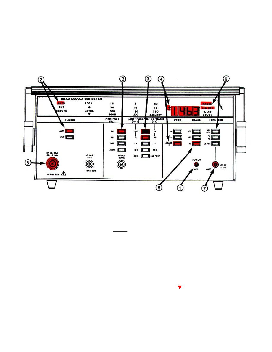
Place POWER-OFF switch in POWER position.
NOTE
In steps (2) through (4) and (6) below the annunciators will light as the switches are depressed.
Step (2)
Depress the TUNING AUTO switch.
Step (3)
Select the HIGH-PASS (Hz) and LOW-PASS (kHz) switches for full scale deviation to be displayed. With
OUT-IN switch depressed, select the respective DE-EMPHASIS (us) filter by depressing 50, 75, 750 or 6
dB/OCT switch depending upon the characteristics of the FM signal under measurement.
Step (4)
Depress the PEAK +, PEAK -, or PK-PK switch depending upon the FM modulation measurement to be
made.
2
Step (5)
Depress the RANGE 300, 100 or 10 switch for full-scale deviation to be displayed.
Step (6)
Depress the FUNCTION kHz DEV switch.
Step (7)
Turn the AUTO SET TO 10.00 control fully counterclockwise to the AUTO position.
Step (8)
Connect the rf signal to be measured to the RF IN connector.
The LOCK annunciator will stop flashing and the LEVEL (signal ) annunciator will extinguish if the rf
Step ( )
level of the input signal is within the correct level range and the frequency of the input signal is within the
acceptable frequency range.
Step (10)
Read the kHz DEV (deviation) from the LED display.
2-17


