TM 11-6625-2629-14&P
250 to 500 MHz.
Band D . . . . . .
......
(kHz) at radio frequencies (rf) from 20 to 1,000
500 to l,000 MHz.
Band E . . .
....
megaHertz (MHz). The modulation frequency
12 MHz
If . . . . . . . . . . . . . .
......
may be from 50 to 70,000 Hertz (Hz). The
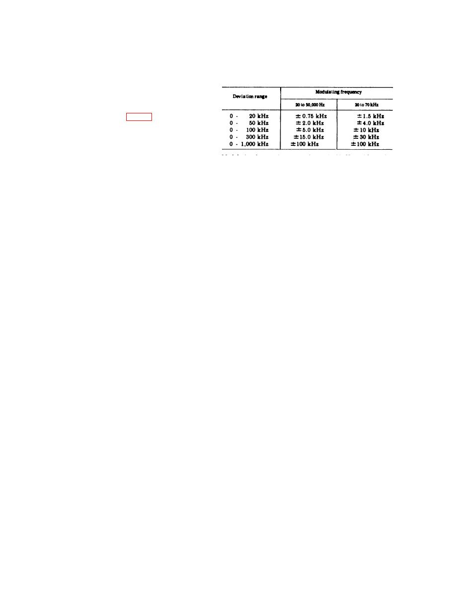
20, 50, 100, 300, 1,000 kHz.
Deviation, . . . . . . . .
......
equipment operates on either 115 or 230 volts
full-wale
alternating current (at), 10 percent, 50 to 420
Hz.
1-8. Description
The modulation meter (see fig. 1-1 ) consists of a
p a n e l - c h a s s i s assembly with a removable
louvered dust cover. The dust cover is attached to
the chassis with four captive screws at the rear.
T h e equipment may be rack mounted in a
Modulating frequencies . . 50 to 20,000 Hz, with carrier
standard 19-inch-wide equipment rack. All
f r e q u e n c i e s of 20 to 100
operating controls and connections are located on
MHz, 250 to 70,000 Hz, with
the front panel. The power cord is permanently
carrier frequencies of 100 to
attached to the chassis and a plug storage
1,000 MHz
receptacle is provided at the lower right side of
Input sensitivity . . . . . . . . . 0.005 volt required for limiting
Input impedance . . . . . . . . 50 ohms
the front panel. The modulation meter is shipped
Voltage standing . . . . . . . . . . L e s s t h a n l . 3 t o l o v e r t h e
in a metal transit case. The lid for the transit case
range of 20 to 1,000 MHz
wave ratio
has compartments for the running spares.
10% of indicated value
Carrier shift . . . . . . . . . . . . . .
accumcy
1-9. Differences Between Models
A m p l i t u d e m o d u l a t i o n . , Operation w i t h a m p l i t u d e
The modualtion meter described in this technical
m o d u l a t i o n of 50% is not
manual was manufactured under type designation
affected
Stability . . . . . . . . . . . . . . Local oscillator drift does not
ME-57A/U. Previously manufactured units were
exceed 200 cps l fter 30-
designated ME-57/U. These units are similar in
minute warmup
appearance, function, and technical capability.
Audio output . . . . . . . .
1 volt ac rms corresponding to
As a very brief synopsis of physical and electrical
40 kHz deviation on the 0.50
differences: ME-57A/U employs an integrated
kHz deviation mnge
A u d i o distortion .
Harmonic distortion does not
circuit in place of four if. amplifiers of the ME-
exceed 0.5 percent up to 900-
57/U; ME-57A/U employs improved tube types;
kHz deviation
ME-57A/U incorporates all field modifications
Noise and hum.... .
63 dB below 1 volt at 40-kHz
applicable to the ME-57/U; and the ME-57A/U
deviation
. 1 1 5 o r 230 volts ( 10), 50
Power
input
.
.
includes circuit changes to accommodate the
to 420 Hz
requirements
integrated circuit and other minor circuit im-
140 watts
Power consumption
provements. Technical data for ME-57/U is
Weight ., . . . . . . . . . 57 lb
covered in TM 11-6625=400-12 and TM 11-6625-
Environment
400-35.
Temperature
O p e r a t i n g . . . . . . . . 4F to +125F
1-10. System Application
(20"C to +51.6"C)
Storage . . . . . . . .
65F to +160"F
The modulation meter may be used as a portable
(54C to +73"C)
test equipment for general use or may be per-
Humidity . . . . . . . . . . To 95% (non-conducting)
manently mounted in an equipment rack with a
transmitter to provide a constant check of the
1-14. Items Comprising An Operable Equipment
performance of that transmitter.
The ME--57A/U is a self-contained test set. The
modulation meter measures approximately 19
1-11. Tabulated Data
inches wide, 10% inches high, and 14 inches
13
Number of tubes
deep. The modulation meter is provided with a
Number of integrated
1
circuits
transit case that measures approximately 22 YS
Frequency, rf:
inches wide, 14 Y: inches deep, 16-3/8 inches high,
20 to 55 MHz.
Band A
and weighs approximately 18 pounds (75 pounds
55 to 120 MHz.
Band B
with modulation meter contained inside).
Band C
120 to 250 MHz.
1-2


