TM 11-6625-2616-14
OPERATION UNDER USUAL CONDITIONS
Section Il.
Starting Procedure
Make sure that the instructions contained in
fore this procedure is started.
a. Preliminary. Set the front panel controls
as follows:
Control
Position
PWR ON pushbutton switch . . . . . . . . . . . . . .
Out
VAC pushbutton switch . . . . . . . . . . . . . . . . . . .
Out
VDC pushbutton switch . . . . . . . . . . . . .
In
AUTO RNG pushbutton switch . . . . . . . . . . . .
Out
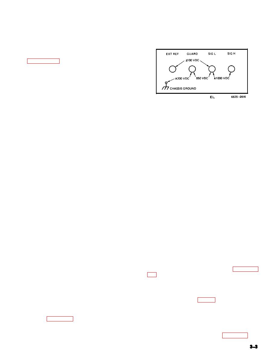
inputs of AN/GSM-64A without causing damage.
RNG CHNG pushbutton switch . . . . . . . . . . . .
Out
Out
R(%) Pushbutton switch . . . . . . . . . . . . . . . . .
f. Connect black-covered clip of test lead set
EXT REF VDC toggle switch . . . . . . . . .
Any
to dc common of voltage source and red-covered
b. Starting.
clip to voltage source.
(1) Plug power cord connector into selected
ac outlet.
automatically, displaying the voltage, decimal
(2) Depress PWR ON pushbutton switch.
point and polarity of the input to the SIG H
Allow 30 minutes for instrument warmup.
jack with respect to the input of the SIG L jack.
h. To select a voltage range manually, de-
3-5. Measurement of DC Voltage
press AUTO RNG pushbutton switch, bringing
a. Be sure that the VDC pushbutton switch
it to the "out" position. Note position of decimal
is in the "in" position.
point. Depress RNG CHNG pushbutton switch
as required to reach desired range.
b. Depress AUTO RNG pushbutton switch.
c. Plug connector of test lead set (P/N 34-
3-6. Measuring DC Voltage Ratio
65) into SIG H and SIG L input jacks.
a. Depress the R(%) pushbutton switch.
NOTE
b. Insert yellow plug of test lead (P/N 34-
A small polarity tab sticks out from
66) into EXT REF input jack of instrument.
the connector nearest the SIG L plug;
i.e., the tab sticks out to the left of
c. Place EXT REF VDC toggle switch in pro-
the operator when the connector is
per position as determined by external reference
properly installed.
voltage to be applied; the switch must be in the
10-1 position for an input of from 1 volt to
d. Insert blue plug adjacent to connector into
10 volts and must be in the 100-10 position
GUARD input jack.
for an input of from 10 volts to 100 volts.
black-covered
e. Connect blue-covered and
clips of test lead set together.
input voltage source as described in paragraph
3-5c through f.
WARNING
If high voltages are to be measured,
CAUTION
use extreme caution. Serious injury or
Do not apply more than 100 volts
death may result from contact with
between the EXT REF input jack and
terminals connected to high voltage
SIG L input jack (fig. 3-2).
sources.
NOTE
CAUTION
The AN/GSM-64A makes a three-ter-
See figure 3-2 for maximum voltages
minal measurement in the ratio mode.
which may be applied to the input jacks
Therefore, a common connection be-
of the instrument without causing dam-
tween the input source and the refer-
age.
ence source is required. See figure 3-3


