TM 9-4935-282-34
803D
(3)
500 VDC Reference Supply Calibration.
c. AC TO DC CONVERTER CALIBRATION. The DC
(a) Perform
preliminary
calibration
Differential Voltmeter section of the 803D must be within
procedure as stated in paragraph 4-4b (1).
specifications before the AC to DC Converter can be
(b) Center CALIBRATE control at its center
accurately calibrated. The AC to DC Converter must be
of rotation.
calibrated in the following order.
(c) Set NULL switch to 10 and voltage
readout dials to 499.9 10.
(1)
Preliminary Calibration Procedure.
(d) Apply 500 volts DC (+0.005%) to
(a) Zero instrument as stated in paragraph
voltmeter.
(e) Adjust 500V ADJ control R121 for a null.
(b)
Set switches on 803D as follows:
(f) Set NULL switch to 0.1 volt.
RANGE
500
(g) Null meter by adjusting CALIBRATE
NULL
0.01
control.
AC - DC polarity
AC
(h) Advance OPERATE-CALIBRATE switch
voltage readout
499.9 10
against spring tension to CALIBRATE and null meter by
dials
adjusting REF CAL ADJ control R318.
(c) Check for excessive converter output
noise as follows: set RANGE switch to 0.5, NULL switch to
(4)
Range Divider Calibration.
0.01, AC - DC polarity switch to AC, and all voltage readout
(a) Perform
preliminary
calibration
dials to 0 (zero); short input terminals of 803D; if the meter
procedure as stated in paragraph 4-4b (1).
needle is not within 150 microvolts (7-1/2 small divisions) of
(b) Set switches on 803D as follows:
null, converter noise is excessive and the trouble must be
RANGE
50
corrected before proceeding with calibration; if trouble occurs it
NULL
0.01
is usually the result of the input tube (V501), the filament
voltage read-
49.9910
supply, or the 500 volt supply being noisy; remove short from
out dials
input terminals.
(c) Apply 50 volts DC (+0.005%) to
(d) Allow 803D to warm to equilibrium
voltmeter.
temperature inside its case (about 1 hour). Meanwhile,
(d) Null 803D meter by adjusting 50V DC
proceed with step (e).
ADJ control R323.
(e) Set up the necessary equipment to
(e) Set RANGE switch to 5 volts.
provide 500, 50, 5, and 0.5 volts AC with an accuracy of at
(f) Apply 5 volts DC (+0.005%) to
least 0.03% at frequencies of 400 cycles, 10 kilocycles, and
voltmeter.
20 kilocycles with less than 0.1 total harmonic distortion.
(g) Null 803D meter b adjusting 5V DC
y
Proceed as follows: connect equipment as shown in figure 4-5;
ADJ control R326.
turn on all test equipment and allow it to warmup to equilibrium
(h) Set RANGE switch to 0.5 volts.
temperature (about 1/2 hour; adjust DC power supply voltage
(i) Apply 0.5 volts DC (+0.005%) to
until differential voltmeter indicates rms value of AC voltage
voltmeter.
(j) Null 803D meter by adjusting 0.5V DC
ADJ control R329.
This completes the DC differential voltmeter calibration.
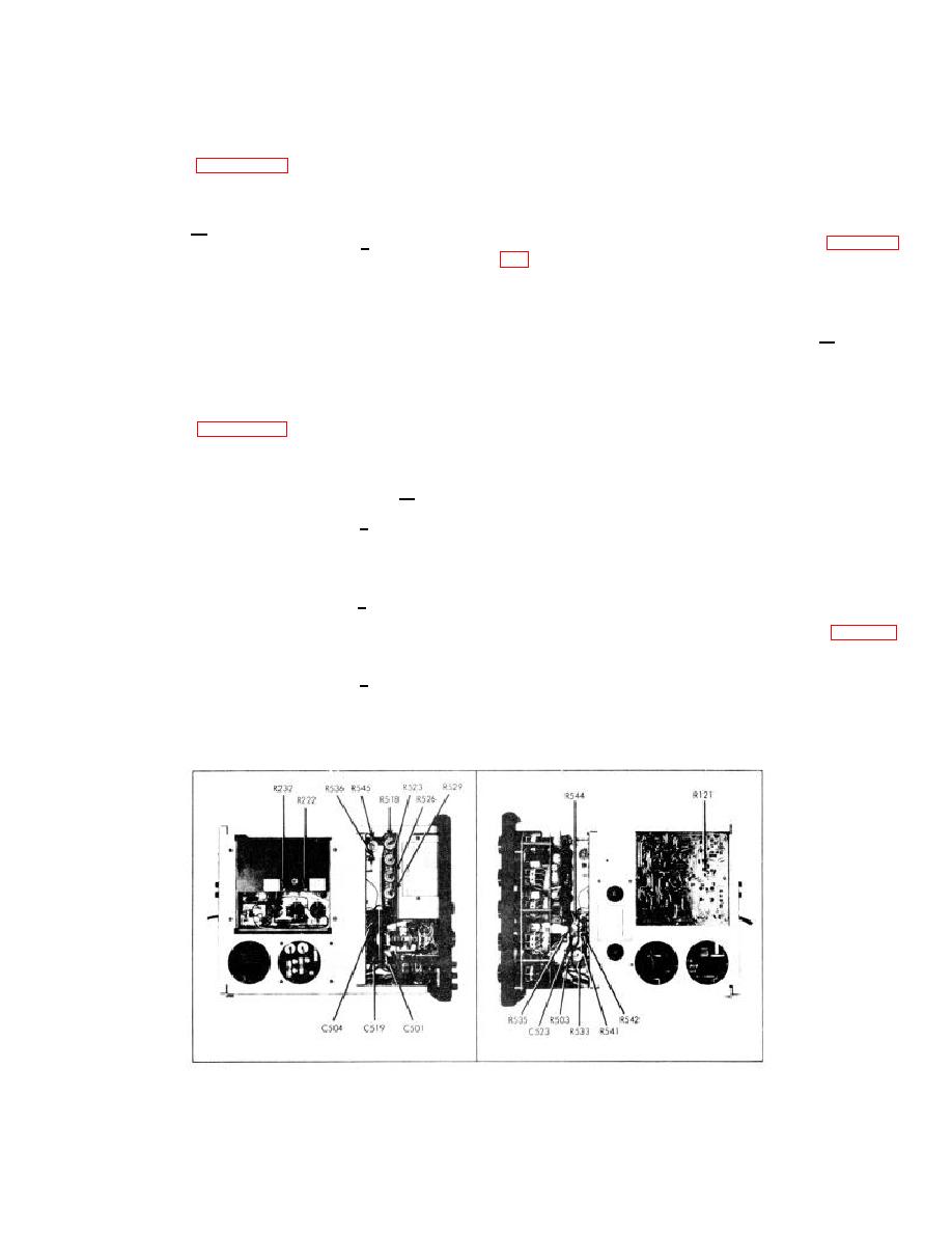
Figure 4-4. ADJUSTMENT LOCATIONS
4-6


