TM 11-6625-524-14-2
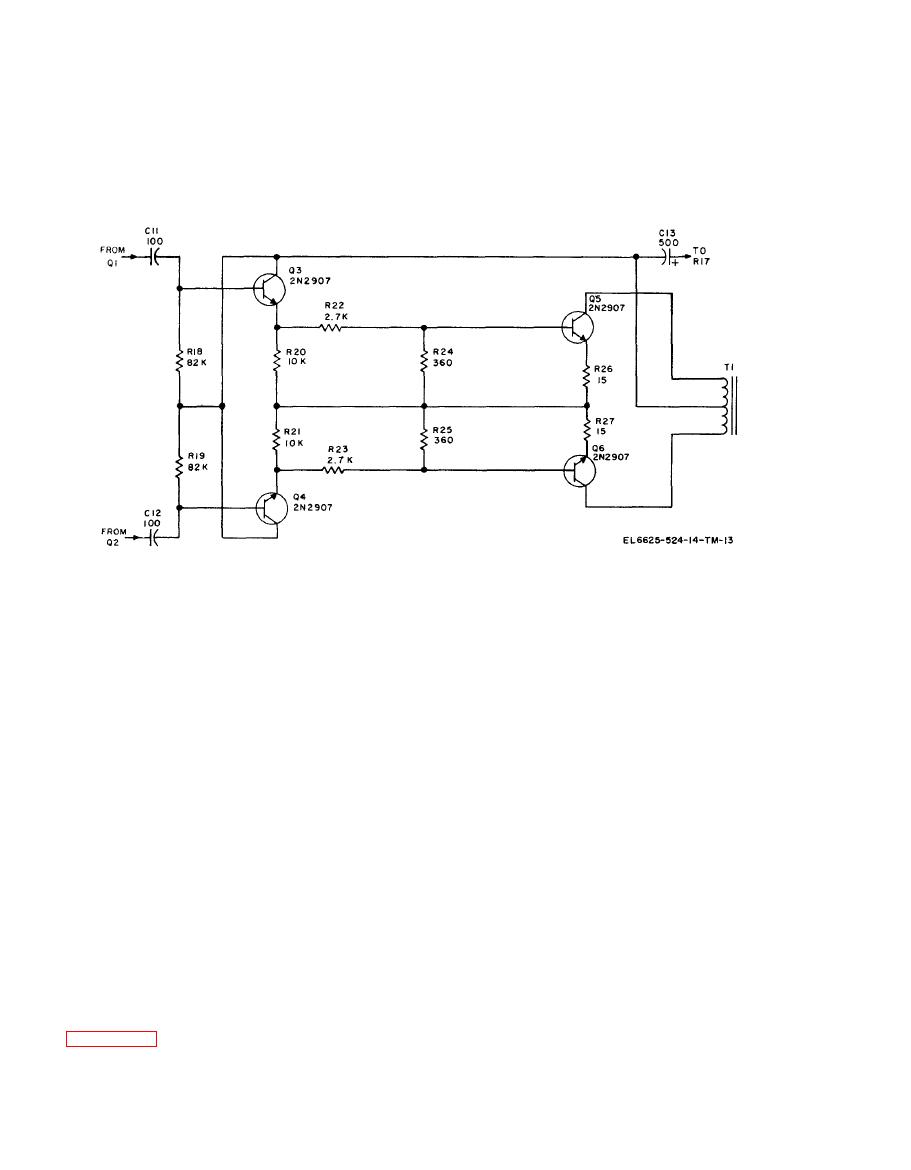
followers 3A2Q3 and 3A2Q4. The amplifiers
3A2Q5 and 3A2Q6 amplify this square wave, and
it is coupled to the synchronous demodulator via
The 94-Hz square wave from the modulator driver
is sampled by the amplifier stages via emitter
3A2T1 .
of 3A2T2 and filter capacitor 3A1C6. For low
input levels, 50 percent of full scale and lower, the
A portion of the dc output voltage from the
signal passes through 3A3R22, 3A3R21,
synchronous demodulator is fed back to the dc
3A3CR6, 3M1, and 3A3R5. At low levels, the
modulator to provide the excellent gain stability
resistance of 3A3CR6 is fairly high and the
of the voltmeter. This feedback ratio is deter-
c u r r e n t through the circuit is limited. By
mined by values of a resistor and potentiometer
paralleling 3A3R21 and 3A3CR6 with 3A3R17
connected in series and switched through section
and 3A3R25, an exact adjustment of the meter to
H of range selector switch 3S2. One of the three
a point corresponding with the input voltage is
thermistors mounted in the rf probe is switched in
possible. For higher levels, 70 percent through
series with the previous combination by means of
100 percent of full scale, 3A3R1, 3A3R35, and
sections C and E of 3S2. The dc feedback con-
3A3VR2 paralleled with 3M1 and 3A3R5 provide
trols, marked mid on the calibration plate, are
adjustment of the meter to correspond with the
used for accurate calibration of the midscale for
incoming signal. To adjust the midscale point,
each range. The appropriate feedback ration is
the main dc feedback resistors are utilized.
selected when switched to the desired range.
b. Indicating meter 3M1 employes a taut band
movement that is rated at 0-500 microampere (ua)
Circuit
dc. It also utilizes a mirror-backed scale to
The dc output of the diodes in the probe is
minimize parallax errors.
basically nonlinear with respect to the rf input
c. Resistor 3A3R5, in series with 3M1, is
l e v e l . In order to achieve a linear output
connected to the circuit via 3J2. For external
characteristic, correction networks are employed.
monitoring purposes, when a plug is inserted in
Their function is to expand the lower end and
3J2, 3A3R5 is switched out of the circuit and the
compress the upper end of the meter scale. Refer
external monitor must provide the 2K ohms series
to figure 5-8 for better understanding of the
load. This value should be within 1 percent to
circuit. The switch is at the 0.001 volt scale.
maintain the rated calibration accuracy of the
a. The rectified dc, proportional to the dc input
signal, appears at the center tap of the secondary


