TM 11-6625-524-14-2
e. The main controls required to operate the
of suitable null networks, measurement of the
voltmeter are on the front panel. Several minor
controls are on the rear panel.
formed without the attendant errors of average-
type meters. The voltmeter is also useful as an rf
n u l l detector for bridge measurements and
analogous techniques when a sensitivity in the
Measurement range
300 uv to 3 volt.
order of 200 uv will suffice.
Frequency range
.20 KHz to 600 MHz.
b. Supplied with each instrument is a general
Full scale ranges . . . . . . . . 0.001.0.003.0.01, 0.03,0.1,
0.3, 1.3 volt.
purpose rf probe, 50-ohm adapter and probe tip.
Accuracy . . . . . . . . . 0.001 range 10 percent of
The adapter is fitted with a type bnc coaxial con-
only
full scale to
nector and provides a 50-ohm termination with a
200 MHz
low vswr up to 600 MHz. The probe tip is useful for
15 percent of
direct measurement to approximately 250 MHz.
full scale
However, a short wire should be substituted for
above 200
the ground lead when using above 100 MHz to
MHz.
minimize the effects of ground lead inductance.
0.00:3 range and 5 percent of full
Above 250 MHz, the probe may be used directly
scale to 200
above
MHz
without the tip, but the connecting leads must be
extremely short to avoid resonant effects. Nor-
10 percent of
mally, the rf probe is used with the 50-ohm adapter
full scale
above 200
in a coaxial system for accurate measurements
MHz.
above 100 MHz.
c. The rf probe with its full-wave crystal detect-
Input inpedance . . . . . . . .See figure 1-3.
ing circuit produces a true rrns response without
Decibel range (red scale) . ..0 to 70 db in 10 db steps.
Maximum
vswr
... 1.2 up to 600 MHz.
turnover, or harmonic errors for all voltage levels
Power requirements . ...115/230 volt, 55 to 65 Hz. 12
below 0.03 volt, gradually changing to peak-to-
watts.
peak reading (calibrated in rms) at approximately
Dimensious . . . . . . . . . . . . . . . 9 inch H x 6 inchW x 11
.
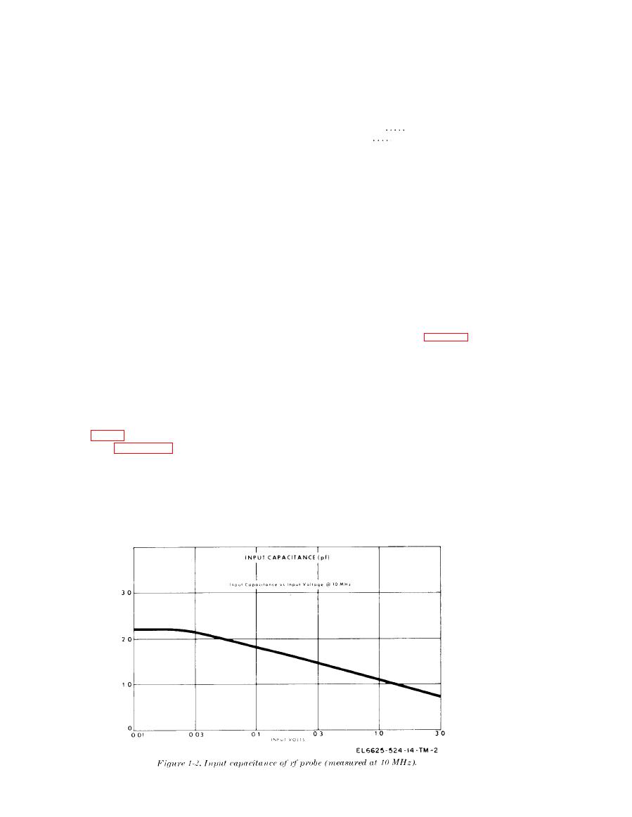
1.0 volt. The probe has a shunt capacitance of ap-
inch Doverall (handle
proximately 2.2 water holding energy (pF) at levels
folded).
Weight . . . . . . . . . . . . . . . . . . .. 10lb.
of 0.3 volt or higher, decreasing slightly at levels of
0.1 volt or less (fig. 1-2). The shunt resistance com-
1-7. Items Comprising an Operable Equip-
ponent shown in figure 1-3 is a variable factor,
ment
depending on the voltage and frequency. A decibel
a. Voltmeter, Electronic ME-247C/U.
(db) scale in red on the panel meter and range
b. Probe, P/N 900-2000B.
switch provides a convenient means of expressing
c. 50-ohm Adapter, PIN 900-2050A.
relative voltage measurements.
d. Probe tip, P/N 900-2002.
d. A screwdriver zero control on front of the
e. Power cord, P/N 800-5121.
meter provides zero adjustment of the meter
f. output plug, Switchcraft Inc., P/N 60.
pointer.


