TM 11-6625-444-14-1
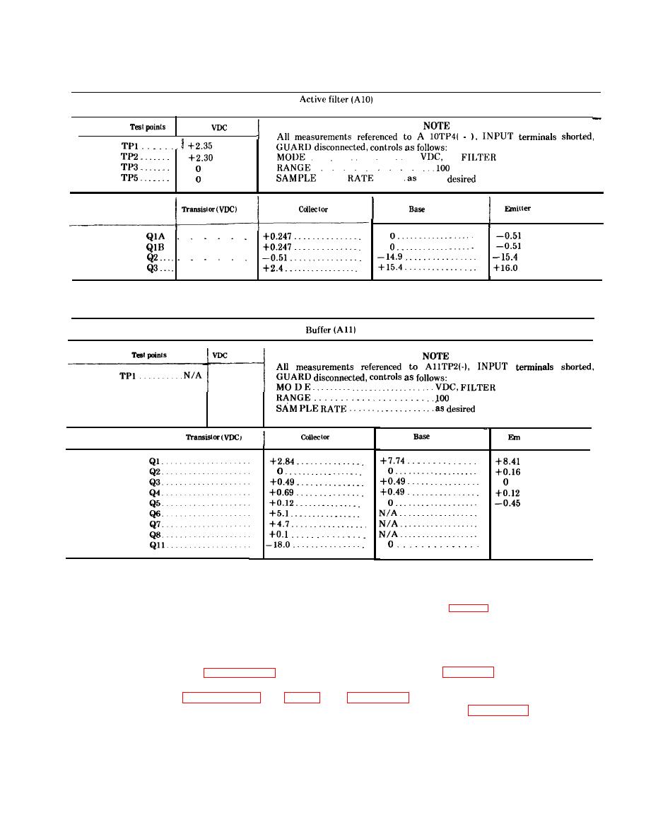
+4.9
+4.9
+4.9
o
--
NOTE
All voltages measured with battery powered differential voltmeter (table 6-1).
6-4. Part Locations
6-3. Schematic Diagrams
Location of assemblies and troubleshooting test
A schematic diagram of each assembly in the
points are shown in figure 6-1. Calibration ad-
voltmeter is contained in figures FO-2 through
F O - 9 . An interconnect diagram and wiring
justment and test point locations are shown in
diagram is shown in figures FO-10 and FO-11,
assembly are shown in figures 6-3 through 6-13.
respetively. All diagrams are located at the rear
of this manual


