TM 11-6625-2629-14&P
Table 7-2. Resistance Measurements Continued
Point of measurement
Isolating procedure
Normal indication
.
B e t w e e n ground and pin 6 of
Resistance
should
be
If resistance is less than 10K, check all screen
XV15.
approximately 10K; reading will
b y p a s s capacitors (fig. 7-3 and FO-2). If
b e determined by setting of
resistance is higher than 10K, check R130 for
R130.
open (fig, 7-2).
1
.
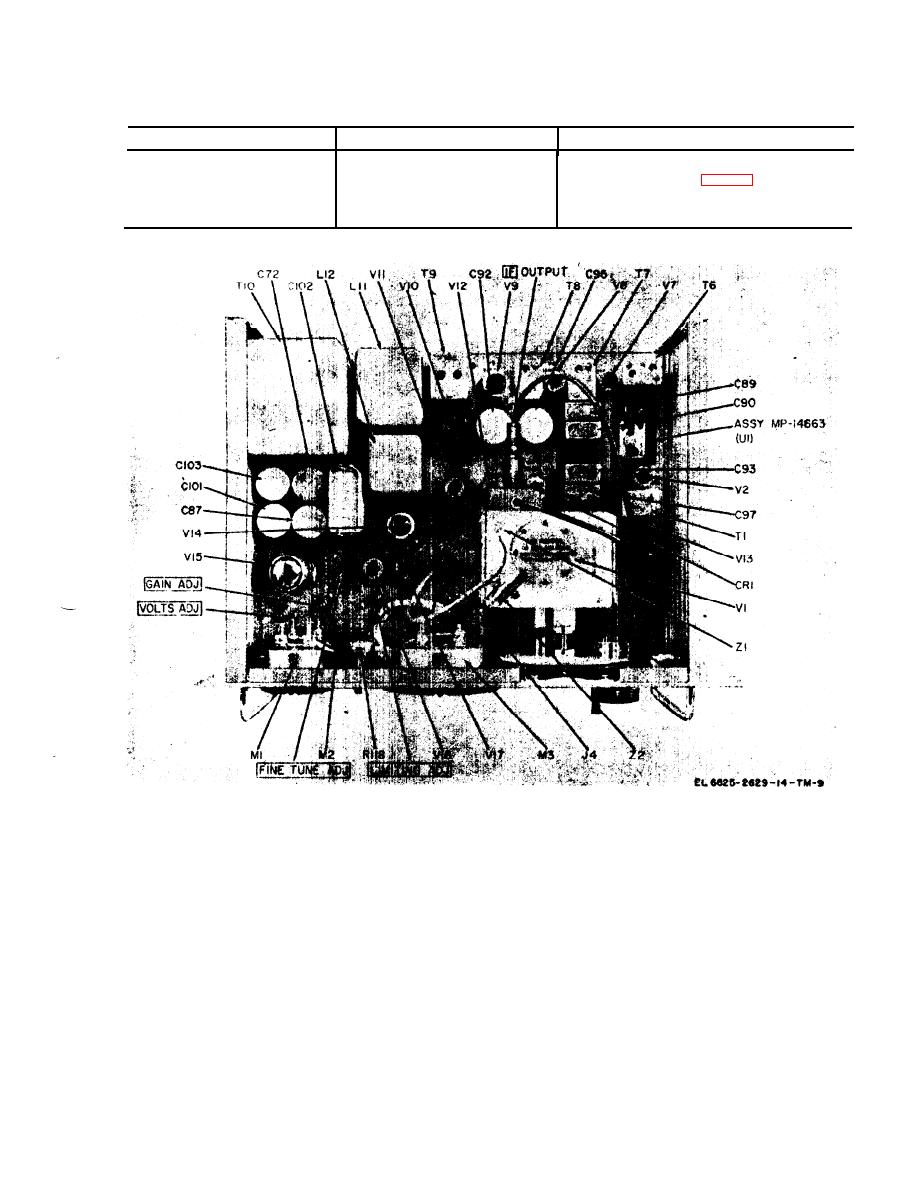
Figure 7-1. Modulation meter chassis, parts location, top view.
7-3


