have been properly matched, tile singal generator
1
each RF Cable Assembly CG1471/U (9")
is used to make adjustments, alinement and final
1
each Adapter Connector UG636A/U
testproccdurcs.
1
each Adapter Connector UG971/U
each Electrical Dummy Load Case CY-
1
2. Components. Electronic Equipment Main-
1892/URM
tenance Kit MK-288/URM consists of the follow-
ing components:
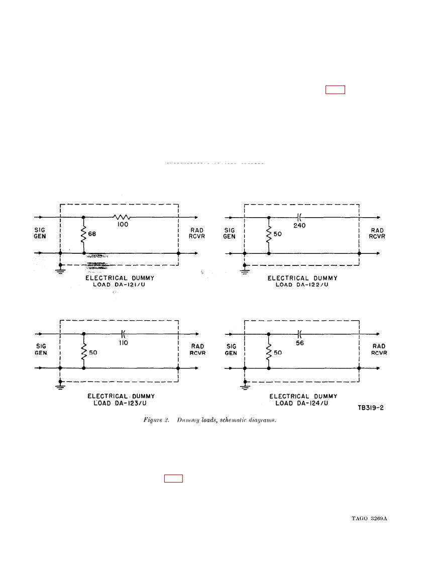
1 each Electrical Dummy Load DA-121/U
impedance-matching substitutes for balanced
(rhombic or doublet) or unbalanced (whip or
1 each Electrical Dummy Load DA-122/U
1 each Electrical Dummy Load DA-123/U
straight wire) antennas in the following radio
receivers:
1 each Electrical Dummy Load DA124/U
Dummy
load
-.
Radio receiver
Antenna type
DA-121/U - - - - - - - - - - - R-390/URR, R-390A/URR, R-391/URR, R-392/ Doublet or rhombic.
URR.
DA-122/U- - - - - - - - - - - - - - - - R-389/URR
Straight wire (long).
DA-123 /U- - - - - - - - - - - - - - - - Radio Receiving Set AN/G RR-5 - - - - - - - Straight wire (medium) or whip.
DA-124/U - - - - - - - - - - - R-390/URR, R-390A/URR, R-391/URR, R-392/ Straight wire (short) or whip,
URR.
and are used to connect the dummy load between
a. The dummy load must be
4. Connections.
the generator and the receiver. Connect the long
connected between the rf output terminals (50
cord (3 ft 11 in.) between tile generator and the
ohms) of the signal generator and the antenna
dummy load input. Connect the short cord
input terminals of the radio receiver (fig. 3). The
between the dummy load output and the receiver
output indicator is connected to the output of the
antenna input.
receiver for alinement purposes. Two cords
b. RF Cable Assembly CG-1471/U is used to
CG409/U are supplied with the signal generator
2


