TM 11-6625-599-12
Note: This method will not work when more than
and put back the original tube. Repeat this
one tube is defective in the same circuit.
procedure with each suspected tube until the
defective tube is located.
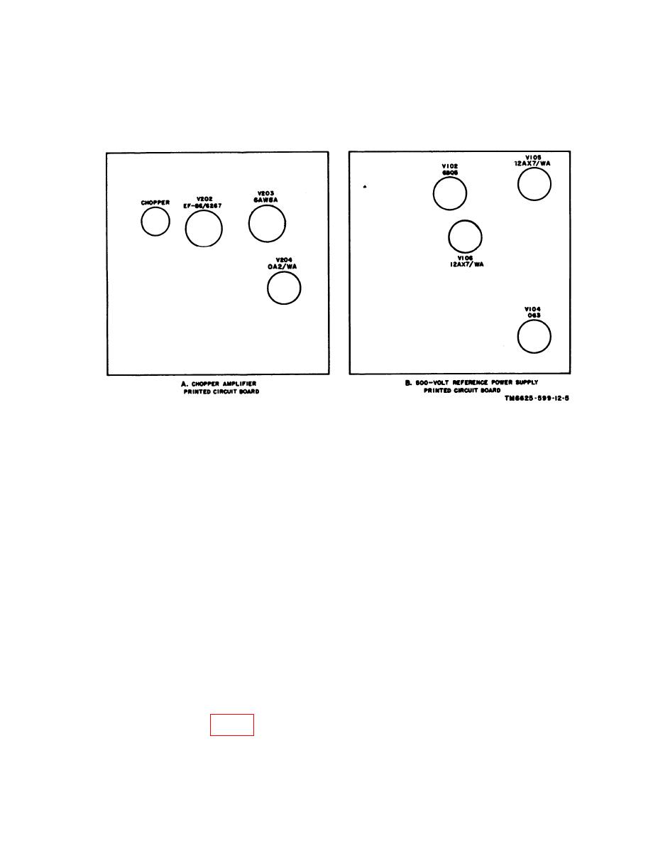
Figure 5.
Voltmeter, Electronic AN/USM-98A, tube location.
g. Press the sides of lampholder together
3-14. Replacement of Decimal Point
and remove the lampholder from the mounting
Indicator Lamp
plate.
a. Remove the two securing screws at the
h. Remove the paper shield from the decimal
rear of the vtvm.
point indicator lamp.
b. Pull the chassis out of the case.
i. Press in on the defective decimal point in-
dicator lamp and turn it counterclockwise to
c. Remove the four screws that secure the
front panel assembly to the chassis.
unlock.
j. Pull the defective indicator lamp out and
Caution: Be careful when handling the
replace it. Press the new decimal point indi-
front panel to prevent damage to the wiring.
cator lamp into the socket and turn it clockwise
d. Gently lift the front panel assembly from
to lock.
the chassis and set it face down in front of the
k. Replace the paper shield and press the
chassis.
sides of lampholder to insert the shield in the
mounting plate.
e. Remove the screws that secure the range
resistor and the five-decade attenuator printed
l. Replace printed circuit boards on front
circuit boards to the front panel assembly.
panel.
m. Secure front panel to chassis.
f. Push the printed circuit boards aside
n. Replace chassis in and and secure with
enough to allow access to decimal lampholders
two screws.
PL1, PL2, PL3, or PL4 (fig. 6).
21


