TM 11-6625-599-12
are present and the NULL switch is
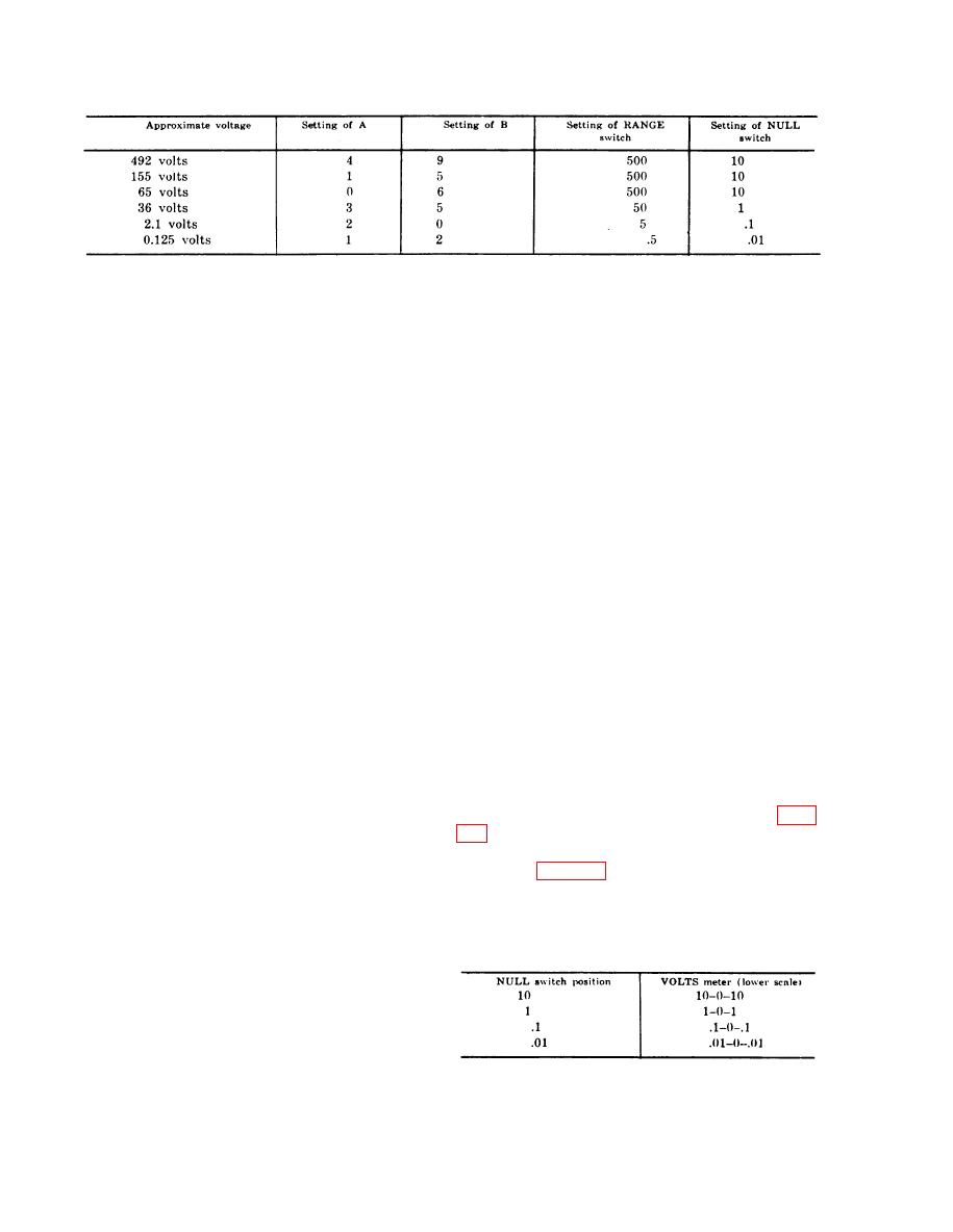
Note: Set the voltage-divider switches slightly below
the approximate value as indicated in the chart above.
set to .1 or .01, additional filtering
may be required.
(3) Advance voltage-divider switch B un-
(2) If the ac component is of a single fre-
til the VOLTS meter indicator deflects
quency, a twin-T-filter is effective
to the left, and then back one step to
and has the advantage of low total
return the indicator to the right side.
series resistance. If the ac compo-
(4) T r i m voltage-driver s w i t c h e s C
nents are of variable frequency, an
through E as required to obtain 0 in-
ordinary low-pass filter may be used.
dication on the VOLTS meter.
In either case, the capacitors used to
(5) Determine the voltage being meas-
form the filter should have a very
ured from the voltage-divider indica-
high leakage resistance.
tors; be careful to note the location
of the decimal indication.
the ac voltage component may vary
E x a m p l e : V o l t a g e - d i v i d e r indicators A,
from equipment to equipment, a spe-
B, C, D, and E indicates 3, 8, 6, 5, and 9,
cific filter cannot be specified here.
respectively. I f t h e R A N G E s w i t c h w e r e
Presumably, if a filter is required, it
on 500 and the NULL switch on 10, the
will be specified in the technical man-
d e c i m a l point indicator between C and D
ual covering the equipment under
would be illuminated and the voltage meas-
test. Losses introduced by the filter
ured would be 386,59 volts. However, if
the RANGE switch were on 5, the NULl
should be computed as specified in
switch on .1, and the decimal point indicator
the equipment technical manual.
between voltage-divider indicators A and B
i l l u m i n a t e d , the voltage reading would be
2-8. Observing Voltage Excursions
3.8659.
The vtvm can be used to observe excursions
(6) Turn the NULL switch to VTVM.
of a voltage about a given value, such as the
(7) Turn off and disconnect the voltage
variations in the output voltaqe of a dc power
under measurement from the com-
supply. Determine the approximate value of
mon input terminal and the input ter-
the voltage to be observed by using the vtvm
minal.
as a conventional vacuum-tube voltmeter (para
c. Ac Component.
a. Set the vtvm to operate as a differential
(1) A low-pass filter is used to reduce
voltmeter (para 27 ).
any ac present on the dc being meas-
b. Observe the excursions on the VOLTS
ured. This filter has an attenuation
meter. The proper scale to use is indicated by
rate of 330 to 1 at 60 cycles per sec-
the position of the NULL switch as shown in
ond (cps). A 0.5-volt ac component
the following chart:
at 60 cps will be reduced to slightly
over 0.001 volt. This may still cause
a reading of as much as 10 percent of
full scale when the NULL switch is
set to .01 and may be negative or
positive. If larger ac components
14


