TM 11-6625-3059-10
PRINCIPLES OF OPERATION
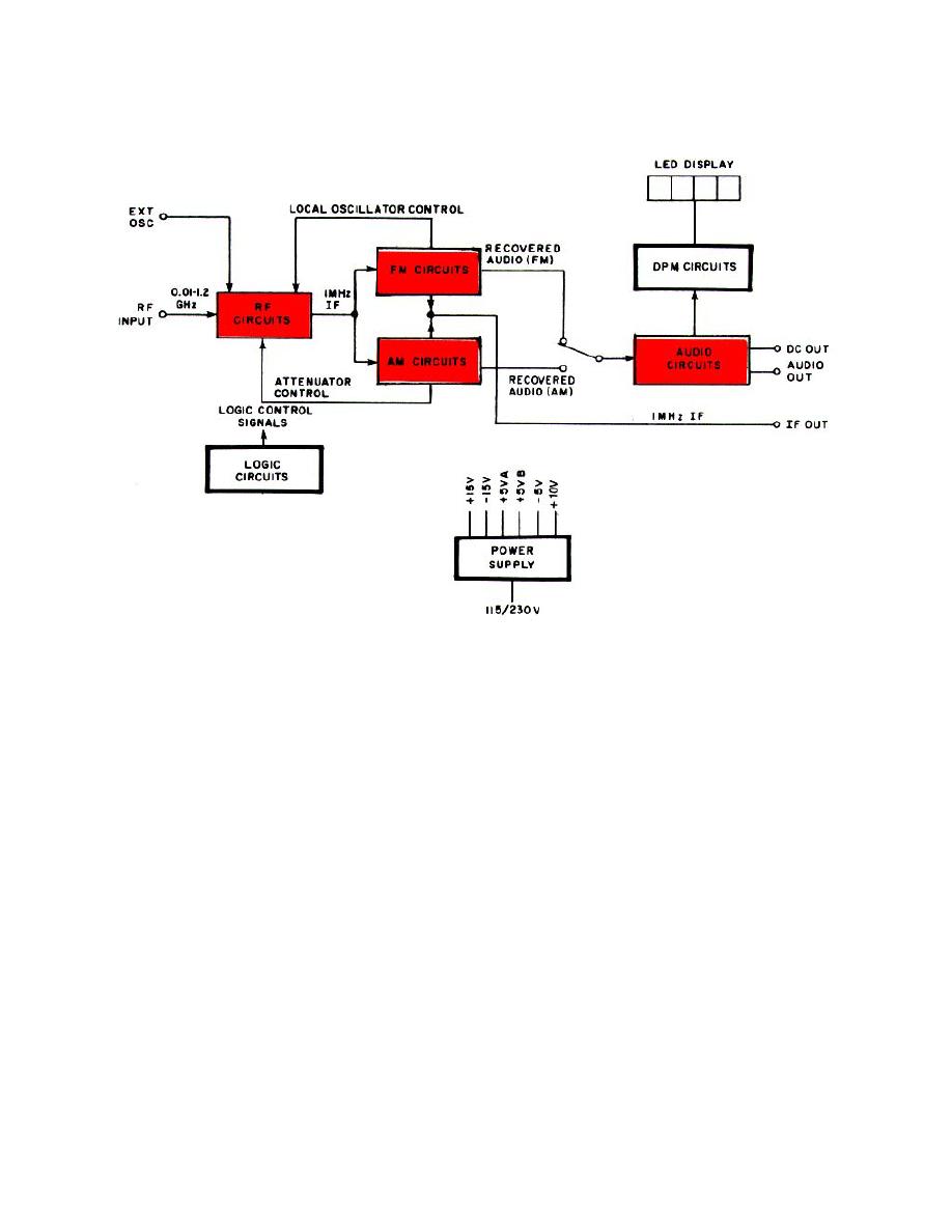
f. Digital Panel Meter(DPM) Circuits. The dc signal information supplied by the audio circuits is converted to a
four-digit display by a precision, dual slope integrator. Multiplexed display signals drive the LED display on the front
panel. Proper display decimal point location is determined automatically by logic circuitry. If the LED display circuits
should overrange, an overrange signal is supplied to the logic circuits.
g. Logic Circuits. The logic circuits convert the front panel switch signals to 5-volt, CMOS-compatible control
signals. These signals are supplied to individual circuits of the ME-525A/USM through a three-state instrument control
bus. The logic circuits also generate multiplexed signals which illuminate control and status annunciators on the front
panel.
h. Power Supply Circuits. The power supply circuits provide regulated, dc voltages. Six power supplies are
required: + 15-volt, + 10-volt, 15-volt, 5-volt, + 5-volt (A), and + 5-volt (B). Two separate + 5-volt supplies are used to
power the analog and digital sections of the M E-525A/USM to ensure the lowest possible residual modulation.
1-10


